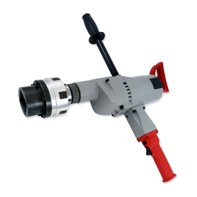
Ensuring equipment and operator safety is critical when using heavy-duty power drills to open and close gate valves, butterfly valves and other high-torque rotary actuators. To this end, the Mach III T4X2R-STH torque-limiting coupling minimizes the risk of machine damage by slipping when the torque exceeds a preset limit, preventing harmful overloads in power drill applications.
This coupling features a #3 Morse taper shaft that directly connects to the drill socket. During operation, torque is transmitted until it exceeds the slip torque setting, which can be specified at the factory before shipment or adjusted manually in the field with a spanner wrench. Once the drill exceeds the set torque, the friction and disc drives slip — and continue to slip — until the drill is powered off. Operation can then be resumed without requiring a reset, preventing high torque from damaging the equipment or jarring the operator.
The T4X2R is supplied with a range of output options for connecting to imperial or metric shafting, square nuts, hex sockets and square sockets. It supports multiple coupling output designs in both steel and aluminum constructions. This coupling also achieves torque up to 2,796 pound-inches and operates up to 1,750 rotations per minute.
The coupling’s compatibility includes:
Standard keyway
Square nut
Square socket
Hex socket
“D” shaft
Installing the T4X2R torque limiter coupling is easy and can be done in minutes. Swapping different coupling outputs is fast and simple — requiring only a hex wrench.
Take a look at the T4X2R and learn more by watching our new video.
Spring-engaged and air-engaged brakes both compress friction and drive discs to restrict motion. However, you might find one is better suited for your application. In a previous blog post, we explored spring-engaged brakes, including their design and use cases. Now, to help you during the brake selection process, we turn to air-engaged brakes.
How Do Air-Engaged Brakes Work?
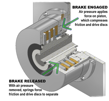
Air-engaged brakes stop rotational motion through the compression of two types of discs — the friction and drive discs — which are normally spaced apart by separator springs. To engage the brake, compressed air pushes the piston rod that compresses the separator springs, pushing both discs together and stopping any motion.
Unlike spring-engaged brakes, the amount of achievable torque in air-engaged brakes isn’t fixed; rather, the more air pressure that is applied, the greater the torque. To disengage the brake, the compressed air is turned off or lowered, allowing the separator springs to expand and push the friction and drive discs apart again.
Ideal Applications
Air-engaged brakes are a good choice for dynamic stopping and cycling applications because they compensate for disc wear over the brake lifecycle. Because the torque isn’t fixed, users can offset friction and drive disc wear by applying more air pressure, pushing the piston rod further and maintaining the same torque.
Air-engaged brakes remain functional until the friction disc wears down to the point that the piston O-ring seals travel beyond the cylinder walls and air leaks out. Keep in mind, these components require a continuous supply of compressed air. Although they can be used to hold a load, if the power fails, so will the brake.
Common Uses
One application for air-engaged brakes is conveyor belts that frequently start or stop. In this example, consider multiple items per zone, creating a load of up to 14,000 pounds with the conveyor moving at 60 feet per minute and stopping every 6 seconds. This application requires the brake to stop the load in 0.25 seconds or within 1.5 inches of motion.
To calculate the minimum brake rating (Tm) required, we’ll need the load weight (W), conveyor velocity (V), coefficient of friction (F) and pitch diameter of the sprocket (Pd). Here are the calculations, where:
W = load weight (14,000 pounds)
V = velocity (60 feet per minute)
G = gravity (32.16 feet per second squared)
T = time (0.25 seconds)
F = coefficient of friction (0.02)
Pd = pitch diameter of drive sprocket (5 inches)
SF = safety factor (1.5)
Tb = braking torque
Tm = minimum safe brake torque rating
$$
T_b = \left(\frac{W \cdot V}{60 \cdot G \cdot T} – F \cdot W\right)\cdot\frac{P_d}{2}
= 3{,}653\ \text{pound inches}
$$
$$
\text{Distance to stop in 0.25 seconds}
=
\left(\frac{V}{60 \cdot 2}\right)(12T)
=
1.5\ \text{inches}
$$
To prevent salmon from swimming into flood drains in the Sacramento River, local agencies built a special hoist system that raises and lowers grated barriers. Part of the assembly is a custom torque limiter that slips the system whenever debris buildup creates an excess of force on equipment. These torque limiters feature a special housing that supports over 250 pounds and can withstand the outdoors 24/7. They also make it easy to adjust the slip torque setting on-site. Thanks to our torque limiters, the hoist system automatically lowers the gates upon overload, protecting the equipment. To learn more, please visit machiii.com.
If your application needs a braking system, how do you know whether it’s better to use a spring-engaged or an air-engaged brake? Both are similar in design — they compress friction and drive discs to restrict motion — but each one has its own ideal use cases. In a new two-part blog post series, we’ll explore the key aspects and applications of both brake types, beginning with spring-engaged brakes.
How Do Spring Engaged Brakes Work?
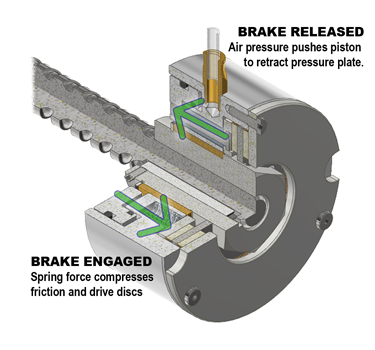
Spring-engaged brakes rely on the compression of two discs — the friction and drive discs. As the disc surfaces meet, the friction force between them stops the rotational motion. The engagement springs expand, forcing a piston to push both discs together and causing the motion to stop. You also need a specific amount of air pressure to push the piston assembly away from the discs and disengage the brake. This air returns the engagement springs to a compressed state, stopping the air supply. Now the brakes are ready again for use. Sometimes, spring-engaged brakes use separator springs to provide a positive separation of the discs to prevent drag and undue friction on the system.
Ideal Applications
The strength of spring-engaged brakes is especially evident in non-cycling applications, where the brake only engages several times an hour or day. Repetitive engagement of the brake can cause the friction and drive discs to thin from wear, requiring the springs to travel further to compress the discs and lowering torque output. In situations where stopping is rare, as in emergency braking systems, spring-engaged brakes are ideal.
A Simple Example
One common application for spring-engaged brakes is holding a lift in position or providing braking force in case of a power failure. The high-capacity lifts that raise automobiles and shipping and air cargo containers are an example. In this case, the lift carries a load of 900 pounds and is driven by a gear motor with a 20-millimeter diameter and five-millimeter pitch ball-screws. The brake needs to hold the lift still when it isn’t in use and will engage when internal sensors detect a zero rotations-per-minute condition in the motor drive.
To calculate the brake parameters for this application example, you’ll need to know the ball-screw lead value, load weight and desired safety factor, where:
L = ball-screw lead (0.1969 inches)
W = load weight (900 pounds)
SF = safety factor
Required holding torque: L x W ÷ 5.65 = 31 pound-inches (lb-in)
Required torque with the safety factor: 31 x 1.75 = 55 lb-in
For more information on spring-engaged brakes, visit our website.
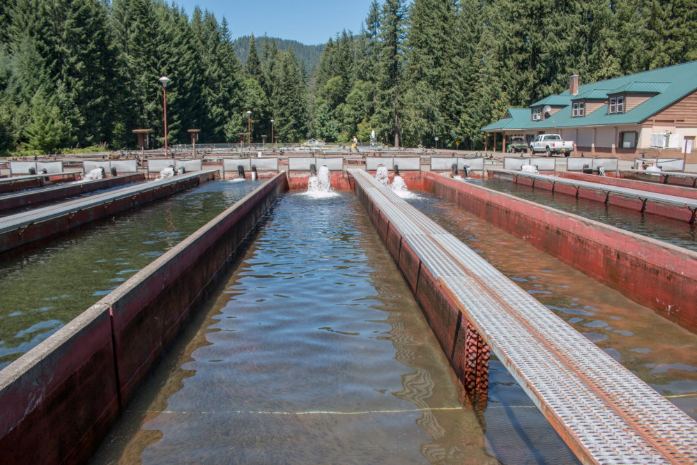
We recently supplied custom torque limiters for a salmon hatchery in Port Armstrong, Alaska. This hatchery uses moving fences — or “crowders” — to push adult salmon from one end of a 50-foot raceway to the other end, corralling the fish for egg and milt harvesting. The hatchery uses a direct drive motor system that must be manually operated.
Here’s how it works. Once the fish density reaches its predetermined limit, the operator turns off the drive. As the salmon are removed from the crowder’s receiving end, the density lessens and the operator turns the drive on again to push more fish forward. In an ideal situation, the operator would activate the crowder, which would continuously push the fish forward as other salmon are removed, thus maintaining a consistent density.
Although the company had friction torque limiters in place, these components required frequent disc replacement. What this company needed was a hands-off motion control solution that could begin slipping once the system reached its preset resistance point, all while inching the salmon forward with constant pressure.
Turn It On and Forget
To meet these application requirements, our engineers designed a custom C5D2K-002 clutch to retrofit the hatchery’s crowder system, enabling the operators to monitor the operation without worrying about manually turning the drive on and off. The clutch incorporates a dual port rotary union for actuation and is sealed for protection against the wet environment. The drive disc is ventilated via an air inlet and filter vent, allowing cool air to flow through the case and dissipating the 213-watt thermal load from the disc’s continuous slipping.
Additional specifications of this custom clutch include:
1,557 inch-pound (in-lb) capacity
Operating pressure of 30–40 pounds per square inch (PSI)
Cooling air pressure at 5–10 PSI
In addition, because the initial rotations per minute specification was higher than needed, the hatchery installed a variable frequency drive (VFD) to reduce the drive motor speed, cutting down the friction temperature from 240° to 120° F. After installing the new clutch, the company has informed us that it has been functioning flawlessly, enabling the hatchery to successfully harvest 50 million eggs with zero problems. Thanks to the hatchery system’s higher efficiency and throughput, our client can now begin its egg-take procedures without worry.
Finding a standard air clutch that will satisfy all your technical requirements can be tough given the diversity of power transmission applications. That’s why our engineers will customize any clutch within our standard catalog to fit your exact needs. To take a recent example, we tailored one of our standard air clutches to retrofit an automotive gearbox torque testing rig.
Torque Inc., a Mach III distributor, had to supply a clutch for a customer’s testing assembly that connected to an automotive gearbox housed within a climate controlled chamber. The objective was to model a vehicle’s inclination using gearing at different operating temperatures under both high speed/low torque and low speed/high torque conditions.
The Trouble With Torque Testing
Initially, Torque’s customer had sourced a competing manufacturer’s clutch and found that the recorded data was not as granular as they had wanted. The data was also inaccurate due to the clutch sticking and slipping. After Torque consulted us, we provided a custom clutch that overcame these challenges.
The C6A4R-001 clutch features two separate cylinders — one small and one large — to satisfy the required torque range of 30:1. Depending on which end of the torque spectrum a customer desires, the air supply can connect to either the small or large cylinder. Additionally, the sticking and slipping of the old clutch was no longer an issue, thanks to our clutch’s low-friction coefficient linings. In terms of torque capacity, the C6A4R-001 small cylinder achieves 3,048 lb-in at 80 PSI, and the large cylinder achieves 9,078 lb-in at 80 PSI.
A Second Clutch With More Torque
Months later, the same Torque customer decided to conduct more testing at a greater torque capacity, requiring that the same testing rig be retrofitted with a new clutch. We designed a second clutch — the CAA4K-001 — with the same length (215 millimeters) and bore size (75 millimeters) so it fit into the testing assembly without modification. The CAA4K-001’s torque capacity is as follows:
Small cylinder: 4,460 lb-in at 80 PSI.
Large cylinder: 17,730 lb-in at 80 PSI.
Thanks to our ability to deliver high-quality custom products, we successfully met Torque Inc.’s research needs. To learn more about our custom clutches, visit our webpage.
Our Mechanical Friction Torque Limiters are designed to slip so that the torque never exceeds a pre-set amount during momentary overload, protecting the drive and other components from damage. A recent application involving pharmaceutical machinery demonstrates these principles and also highlights our ability to design and deliver custom torque limiters quickly.
Friction Creates Challenges on a Conveyor Belt
The company, a pharmaceutical equipment manufacturer, contacted us after breaking four belts while testing a new machine they had designed for a customer. The issue involved a section of the conveyor where packaged pharmaceutical products accumulated against a hard stop. From there, a suction device was supposed to lift the products to another station for transport. However, whenever the products reached this hard stop, friction between the pharmaceuticals and the rollers created a spike in torque, causing the 20-millimeter textured belt that drove the rollers to break. This belt was driven by a pulley that connected to the output shaft on the gearbox.
After investigating the motor, gearbox and belting, our engineers determined that a torque limiter, placed on the gearbox output shaft, would prevent the belt from breaking when set to a slip torque of approximately 100 lb-in. A big challenge, however, was the small amount of space available for this component. The output shaft of the gearbox had a diameter and length of 30 and 80 millimeters, respectively. In addition, the torque limiter had to be able to withstand washdown.
Achieving the Required Torque in a Limited Installation Space
To meet these requirements, we designed a torque limiter that utilizes a stack of Belleville springs to provide the required torque capacity. We mounted the pulley that drives the belt directly on the torque limiter. Due to this design, the company didn’t have to alter the machine frame or reposition any existing components. Rather, the torque limiter fit within the existing space on the gearbox shaft. Outfitted with aluminum, enclosed housing, the torque limiter also successfully met the application’s washdown requirements.
Once we designed this custom torque limiter, we took this project from design to delivery in about five weeks, enabling the company to retrofit its conveyor and deliver the pharmaceutical machinery on time.
Before the development of the Wallace Weir Fish Rescue Facility, adult salmon returning from the sea to the San Francisco Bay faced a perilous situation. Due to the various drainage and flood-control canals in the area, many fish swam into and became trapped in basin drains, where they would die before spawning.
To avoid this outcome, Sacramento Valley organization Reclamation District (RD) No. 108, along with various state and federal agencies, designed a special hoist system that raises and lowers grated barriers called picket weirs. These large barriers let the water flow but prevent the salmon from swimming into the dead-end basins.
Critical to this hoist assembly is a steel torque limiter that automatically lowers the grates whenever debris buildup, caused by flooding, creates a sudden and dangerous spike in force that threatens the integrity of the equipment.
To fit this application’s requirements, our engineers customized a special T8C3K-001 series torque limiter. These B5 flange-mounted units include a nonstandard frame size, have a 55-millimeter input bore and output shaft, and feature a 17,000 pound-inch torque capacity. In addition, these units are:
Strong. The torque limiters feature special housing that supports the dead weight of the actuator and right-angle gearbox for a total of 255 pounds.
Durable. Units can withstand constant outdoor exposure without fail. To this end, the torque limiter’s housing completely encloses all internal components.
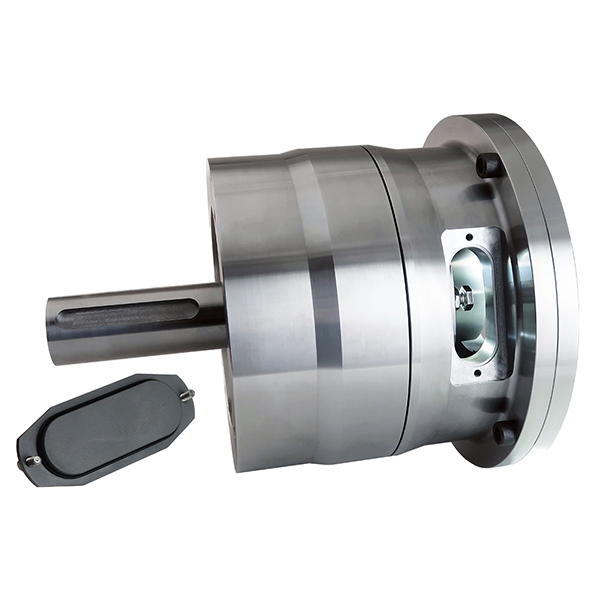
Easily adjustable. Units facilitate on-site adjustments to the slip torque setting. Two ports — covered by sealed, removable panels — provide easy access to the adjustment nuts. After loosening a jam nut with a wrench, users can rotate the nuts to adjust the compression of a disc spring that raises or lowers the slip torque setting. Throughout this adjustment process, the torque limiter remains in place.
We supplied six torque limiters — one for each hoist — that successfully hold the 16 x 29-foot grates in the raised position. If forces against the screen due to debris buildup surpasses 13,500 pounds, then the force travels back through the helical drive and into the torque limiter, where it exceeds the unit’s set 13,000 pound-inch torque value. This causes the torque limiter’s internal friction and drive surfaces to slip against each other, letting the force on the grate unwind the cables, which in turn lowers the barrier and allows the debris to flow over the grate.
To learn more about this application, check out our feature in Design World magazine.
In our last blog post, we highlighted a recent application for which our engineers customized miniature torque limiters for MRI machines. This month, we’re exploring an application that involved a custom servo brake for a fully automatic, nonwoven rewinder machine that processes rolled wet wipes — e.g., disinfecting, industrial, medical, gym, shopping cart and specialty wipes.
The rewinder machine, which processes up to 400 feet per minute and handles web widths from 12 to 42 inches, required emergency stopping brakes for its servo motors. Specifically, these power-off brakes would hold the machine’s steel rotary knife — which is 7.25 inches in diameter and 49 inches long — that perforates the wipes.
In the past, we’ve supplied this customer with small brakes that mount between a 145TC NEMA motor frame and custom 4B flange, with a torque capacity of roughly 300 lb-in. This rewinder machine, however, required brakes that would fit between a 10 HP 215TC NEMA motor and custom 4B flange, and provide 1,200 to 1,500 lb-in of torque.
To meet these requirements, we developed a custom spring-engaged friction brake that releases at 60 PSI and has a torque rating of 2,214 lb-in. These brakes remain energized even in the absence of air pressure and are ideal for any application that requires holding to prevent the rotary motion of a load. You can learn more about how our spring-engaged friction brakes work here.
Learn More About Our Custom Servo Brakes
Over the years, we’ve developed dozens of servo brakes that can be integrated into IEC, NEMA and even non-standard frame motors and gearboxes. We’ve done it all — from providing metric dimensions on one side of the brake and imperial on the other, to connecting a motor of one frame size with a gearbox of another. We’ve also developed custom brakes to fit within tight spaces, meet food safety requirements and much more.
To learn more about some of our latest custom brake solutions, check out our webpage. You can also drop us a line to talk to one of our engineers.
Sometimes, a standard torque limiter simply won’t cut it. At Mach III, our engineers can create modifications of our standard catalog models for many applications — including critical medical equipment. For example, in the following application, we customized our miniature torque limiters for magnetic resonance imaging (MRI) machines. Designed as a retrofit, these units overcame challenges related to wear and backlash during operation.
Aluminum Torque Limiters Create OEM Headaches
We designed and delivered these custom torque limiters for a major original equipment manufacturer (OEM) in the healthcare field. The application required components with nonmagnetic materials, a long wear life and reliable, backlash-free operation.
At the time, the OEM was using aluminum Polyclutch® torque limiters, which incorporated very thin drive discs and 0.02-inch sintered bronze friction discs that wore into the aluminum sleeve, leading to excessive backlash. The torque limiters’ aluminum hub also wore on the shaft it was mounted on, causing additional backlash.
Our engineers overcame these challenges with a custom torque limiter that minimized backlash and provided a longer wear life. Featuring fewer components than the Polyclutch® units, our torque limiters incorporated stainless steel components, which reduced wear compared to the aluminum components. The design also included a Shrink Disc to attach the coupling to the shaft, eliminating a wear-prone keyed connection.
And finally, our engineers machined a thicker drive and friction discs from bronze bar stock. Using our lobed drive geometry, we then connected the drive and friction discs to the drive hub and coupling, respectively. This geometry has a lower tolerance compared to the traditional lug-style drive and friction discs that were used in the Polyclutch® design.
Thanks to these modifications, our custom torque limiters successfully overcame the medical OEM’s wear and backlash challenges. Our engineers can also customize brakes and torque limiters to meet various application requirements for water resistance, food safety and many more.
We’re excited to announce we’ve expanded our standard miniature line of brakes, clutches and torque limiters with our new Miniature NEMA Spring Engaged Brakes Series. These brakes, which include our D2C2R-42H and D2C2R-48H models, are ideal for tight spaces, smaller shafts or applications with light torque requirements.
Features and Specifications
These new miniature brakes include a NEMA frame and enclosed, aluminum housings. In terms of their operation, spring pressure compresses the drive and friction discs, producing a fixed amount of torque. The brake is then released when sufficient air pressure energizes it.
Designed for horizontal mounting configurations, the D2C2R-42H and D2C2R-48H brakes mount between a C-face motor and gear reducer in holding applications. They also function as a failsafe in non-cycling applications.
Notable specifications include:
NEMA frame size: 42C (D2C2R-42H) and 48C (D2C2R-48H)
Dynamic torque: 73 lb-in
Minimum disengagement pressure: 60 psi
Maximum operating pressure: 80 psi
Maximum rotations per minute: 1,750 rpm
Input bore/output shaft: 0.375 in (D2C2R-42H) and 0.500 in (D2C2R-48H)
Our latest miniature spring engaged brakes join our already comprehensive lineup of miniature brakes, clutches and torque limiters. These standard devices are ideal for torque requirements less than 200 lb-in and shaft sizes between 0.3125 and 0.500 in. Clear anodized or stainless housing versions are also available.
To learn more about our new D2C2R-42H and D2C2R-48H Miniature NEMA Spring Engaged Brakes, please visit our product page.
In our last blog post, we explored how to select your clutch to maintain and control web tension in printing, coating, laminating and converting processes. Now, let’s turn to brakes.
As the material being processed in these applications depletes from the input roll, causing the roll diameter to shrink, the torque required to maintain tension on the roll decreases in a linear ratio. Your brake’s torque output must decrease accordingly whether manually or automatically. To determine the required torque range, simply perform the following calculations:
1. Determine the required tension. Tension is measured in pounds per linear inch (PLI).
If the PLI is unknown, then:
PLI = Total Tension (pounds) / Web Width (inches)
For example: 0.5 PLI = 6.5 lbs / 13 in
If the PLI is known, then:
Total Tension (pounds) = PLI x Web Width (inches)
For example: 6.5 lbs = 0.5 PLI x 13 in
2. Next, calculate the required torque range.
The Maximum Required Torque (lb-in) = Total Tension (pounds) x Radius at Full Roll (inches)
For example: 156 lb-in = 6.5 lbs x 24 in
The Minimum Required Torque (lb-in) = Total Tension (pounds) x Radius at Core (inches)
For example: 19.5 lb-in = 6.5 lbs x 3 in
Unless your machine is dedicated to only one product, then you must also consider the PLI range, web widths, core and maximum roll diameters. Determine the required torque range for each product that will be processed on the machine.
Calculating Thermal Load
A brake used on the unwind shaft is typically driven by the machine’s primary drive at a constant input speed, which is expressed in rotations per minute (RPM). As the material feeds into the machine and the roll diameter decreases, the roll RPM increases. Your brake must compensate for the difference between the input and output RPM by slipping. For the unwind section, this process is happening as the required torque decreases. As a result, you only need one calculation to determine the thermal load.
Thermal load is expressed in thermal horsepower (Thp), but it can also be expressed in slip watts or kilowatts depending on the manufacturer:
Heat (Thp) = Total Tension (pounds) x Linear Speed (feet per minute) / 33,000
For example: 0.05 Thp = 6.5 lbs x 250 fpm / 33,000
Be sure to refer to your manufacturer’s thermal ratings to determine if your brake has the heat capacity for the intended process. Unless your machine is dedicated to only one product, then you must also consider the PLI range, web widths, core and maximum roll diameters. Determine the required heat dissipation for each product that will be processed on the machine.
Learn More About Mach III Brakes
If you’re looking for a new brake for your application, or you need a replacement for another manufacturer’s product, our engineering team is here for you. Contact us today. You can also learn more about our standard brakes on our product page.
“How long will it last?” It’s often the first question we’re asked when helping our customers specify a friction clutch or brake. And the answer is always, “It depends.” We’ve seen severe applications where clutches and brakes require replacement wear parts after a few weeks and other applications where they last decades with no maintenance at all.
If you want to maximize the service life of friction clutches and brakes in your industrial machines, here’s an overview of the design, installation and maintenance factors you should keep in mind:
Start with the application details. The most important factor in assuring the maximum service life of a clutch or brake is choosing the right unit for the job based on application details such as cycle rates, revolutions per minute and the torque needed to drive or stop the load. For selection assistance, it’s a good idea to ask for a review by an application engineer at your clutch or brake manufacturer.
Factor in safety. When sizing a friction clutch or brake, add torque service factor to ensure the clutch or brake will have the required torque to drive or stop the load. A service factor of 1.5 to 2 — or 50 to 100 percent more torque than required — is recommended by most clutch and brake manufacturers.
Follow the speed limits. Adhere to the manufacturer’s maximum RPM rating, because excessively high RPM can significantly reduce the life of clutch and brake components such as bearings and linings. The wear effects of rotational speed are particularly pronounced in high-cycle applications. Larger clutches may need precision balancing.
Get some clean air. The quality of compressed air affects the service life of clutches and brakes. It’s important to use only filtered air to eliminate particulate contamination, which can result in worn sealing components and hinder proper cycling of cylinder-piston assemblies. And air needs to be regulated to match supply and demand. If a clutch or brake does its job at 50 psi, don’t operate it at 80 psi. Using the lowest workable pressure will maximize bearing life. Also, if a clutch is transmitting more torque than necessary, the unit may overdrive the system further down the drive train, leading to the breakage or wear of other machine components.
Tip: Periodically readjust air pressure during the wear-in of a new clutch or brake.
Install it right. Following installation instructions is a critical factor in assuring maximum wear life. Common mistakes include mounting the clutch or brake in the wrong orientation and incorrectly installing anti-rotational restraints so that they apply axial force to a clutch, inducing bearing or lining wear. Misalignment in shaft-to-shaft applications can impair clutch or brake function and cause premature wear. If both angular and offset alignment of the shafts cannot be achieved, a flexible coupling is recommended.
Keep chains and belts in order. Chains and belts that are poorly aligned or tensioned are another source of wear and service-life reduction. Chain misalignment, for example, can cause bearing and bushing wear in the pilot of a clutch or clutch-brake. It can also cause sprocket wear. And some misalignment scenarios can result in the clutch moving axially, potentially allowing it to walk off the shaft. Excessive chain or belt tension likewise causes pilot-bearing and sprocket wear — and can allow clutches to continue to be driven when disengaged.
Environment matters. Friction clutches and brakes run best when free from contamination — whose sources include lubricants, brake cleaners, solid particulate and moisture. All of these contaminants can contribute to premature wear or even reduced functionality. For example, contaminants on a clutch drive surface may prevent the unit from full engagement, which can lead to wear and inconsistent torque output. Contact your clutch or brake manufacturer for advice on units that must run in particulate or moisture rich environments. Covered and sealed units that will shield against these contaminants are often available.
Take care of your clutches and brakes. Periodically inspect all your clutches, brakes and combination clutch-brakes for wear. Friction linings will need replacement at a frequency determined by the demand of your application. Repair kits are generally available and contain replacement friction linings along with other typical wear parts such as springs and seals.
Power off brakes are also referred to as holding and fail-safe brakes. They are suitable for applications where a motion system component must be held stationary in the absence of an energizing source. If using electric power brakes, the brake would engage when electricity is intentionally shut off or disrupted by an unexpected power outage. Mach III power off brakes remain disengaged if compressed air pressure is supplied to the brake at the specified pounds per square inch. When air pressure is lost, springs activate to apply force to a series of metal drive discs and composite friction pads providing the torque required to hold the shaft stationary.
How Required Torque Is Determined
The holding power brakes can provide is referred to as torque capacity. Details about how the torque capacity is determined can be found in our Selection Guidelines. For this retrofit application, we used the specifications of the existing motor and the RPM at the brake to calculate that the minimum torque required to hold the shaft stationary was 600 pound inches. Applying a safety factor of 2:1 resulted in a total torque capacity requirement of 1,200 pound inches. Below are the formula and calculation.
Brake Torque Requirement Formula
(Horsepower of the Motor x 63,000/RPM at the Brake) x Safety Factor = Torque Required
Retrofit Brake Torque Requirement Calculation
(0.5 x 63,000/52.5) x 2 = 1,200 pound inches
Why Was A Custom Power Off Brake Required?
Mach III’s standard D6F3G-STH brake could satisfy the torque requirement but would not fit in the available space. The design challenge in this application came from the fact that the brake needed to attach to a shaft which extended only 2.125 inches beyond the frame of the machine. Additionally, the shaft had no keyway. A custom design was necessary to avoid the downtime and expense that would result from field modification of the machine.
The Resulting Custom Brake Design
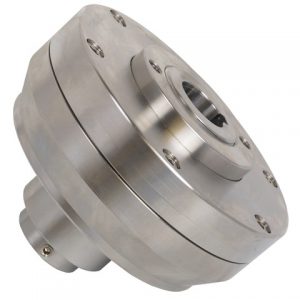
Mach III took advantage of the radial space available to provide the required torque capacity while keeping total axial length of the brake to just slightly over 3 inches. The custom design allowed for quick and simple installation in the field. The brake housing attaches to the machine frame with six bolts on a 6.563 inch bolt circle. Instead of a traditional set-screw and key connection, a Ringfeder shrink disk connects the brake to the shaft.
Click Here to view the detail sheet for this custom power off brake.
To learn more about the Mach III custom design process, and see more custom brakes, Click Here.
Mach III has a number of options for tension control including SensiFlex® tension control clutches and brakes. For applications with low thermal load requirements, standard air engaged brakes with low coefficient friction linings can often be used effectively. Generally, this is a cost saving option; such was the case with this application.
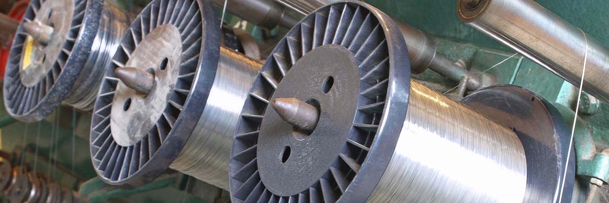
A design engineer was in need of a number of brakes to provide hold back tension on each of the spools in a wire braiding machine. The engineer considered using caliper brakes but they were too large to fit onto the upright that held the spools. Searching for alternatives, the engineer explored the web for other options. He discovered SensiFlex® tension control brakes on the Mach III website, selected a 38BK-ULOW and downloaded a 3D model.
After receiving notification of the download, Mach III’s engineering team followed up to see if they could be of help. Finding that the maximum speed was just 150 feet per minute and the tension required was only 2 pounds, they offered an alternative brake. While the SensiFlex® brake would perform the job from a torque requirement standpoint, it had more thermal capacity than the application required. The B3B1F-001 brake was proposed instead. Not only did this brake fit perfectly on the upright support, the cost was half that of the SensiFlex® 38BK-ULOW brake.
Trying to find a replacement for a Conway Clutch? Mach III founder, Raleigh Becknell, began his engineering career at Conway Clutch where he designed the patented Stationary Air Housing. Mach III clutches are similar to Conway units in function, dimension and torque capacity. By making slight modifications to our catalog standard models, Mach III can provide drop-in replacements for many of the no-longer manufactured Conway clutches. Below are some examples.
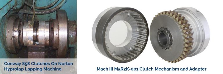
Conway 858 Series Clutch-Adapter Assembly
A Norton Hyprolap lapping machine had a pair of Conway 858 series clutch mechanisms. Mounted back to back on the same shaft, one acted as a brake and the other as a clutch. The Mach III replacement consisted of the clutch mechanism from our standard M5R2K-STH and a customized adapter to match the mounting geometry of the Conway unit. This custom clutch/adapter assembly, Mach III product M5R2K-001, was a drop in replacement. The machine owner purchased two for a total cost of only $3,200 for the retrofit.
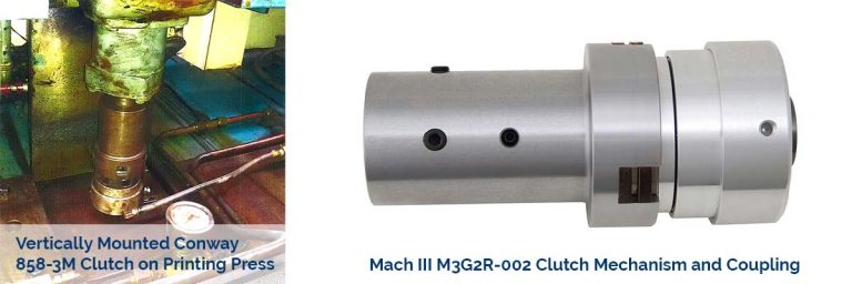
Conway 858-3M Clutch-Coupling Assembly
Mach III created the M3G2R-002 for a Dallas, TX company who was rebuilding a printing press. The press included a Conway 858-3M clutch that was used for controlling tension on the reel. The clutch was seated on a 1.00 inch vertical shaft that extended through the clutch and into the coupling. The top end of the coupling connected to a 1.5 inch shaft. Mach III created a clutch and coupling that replicated the dimensions of the original Conway unit, and added a bearing inside the coupling to facilitate alignment of the two shafts. The Mach III clutch was installed directly in place of the old Conway unit and no additional modifications were necessary.
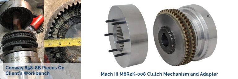
Conway 858-8B Clutch-Adapter Assembly
Many of the Conway clutches in operation are now decades old, and no longer bear identification labels or markings. In this instance, all the client knew was that the clutch was from “Cincinnati” and “10” and 80″ were stamped in the housing. With photographs and key dimensions, Mach III was able to supply a replacement clutch and adapter assembly: M8R2K-008.
Get in touch with our engineers to get started on a Conway Clutch replacement solution for your equipment. While it is helpful to know the current Conway Clutch model number, it is also important that we understand how the clutch is mounted and the function it is performing. Digital photographs or a sketch showing the clutch and how it relates the existing drive are extremely useful.
A maker of cured meat snacks was using a series of studded wheels positioned along a shaft to pull sheets of jerky through a processing machine. Problems arose when the jerky became stuck in any one of the wheels. Although the process was monitored by an operator and the jams could be cleared within a relatively short period of time, the resulting torque spikes were causing damage to other components in the drive system.
With axial space at a premium, Mach III designed a custom torque limiter that is completely enclosed, constructed of stainless steel and uses only 3.8 inches of axial space. The torque limiter is bored to 1.0 inch and slides directly on the drive shaft and is connected with a key and set screw. The studded wheel slides over the pilot of the torque limiter and is bolted to the unit’s face.
The drive plate and friction disc surfaces inside the torque limiter are pressurized by a disc spring that is compressed to transmit a fixed torque amount of 600 pound inches (+/- 10%) from the drive shaft to the studded wheel. When a jam that produces a spike in torque in excess of 600 pound inches, the surfaces slip against one another, allowing the wheel to slip and preventing the torque spike from transmitting to the drive shaft.
Because friction torque limiters do not disengage upon overload, the operator simply clears the jam and the studded wheel immediately resumes driving. No shut down or reset is required.
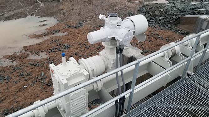
This torque limiter is part of a hoist system that raises and lowers large barrier grates that allow the flow of water from a drainage waterway adjacent to the Sacramento River, but prevent spawning salmon from swimming in. A torque limiter was needed to provide a means of slipping the hoist system – effectively lowering the grates automatically when an excess of force is caused by the build-up of debris preventing damage to the weir structure and equipment.
Unique challenges of this application were addressed through custom design:
Installation between SEW compact helical gear box and SAF77 gearbox
The torque limiter housing has non-standard B5 input and output along with an integral adapter.
The unit must support a 255 pound overhung load.
The housing was specially designed to provide the required support of the SAF77 gearbox and Rototork actuator.
24/7/365 outdoor exposure
The housing provides complete enclosure of the internal components.
The slip torque setting needs to be adjustable onsite.
Two ports covered by sealed, removable panels allow access to the adjustment nuts. After loosening a jam nut with an open end wrench, the adjustment nuts can be rotated to increase or decrease compression of a disc spring which raises or lowers the slip torque setting. The torque limiter remains in place throughout the process.
To view the spec sheet for this torque limiter, Click Here.
The motto of BouMatic, a Wisconsin manufacturer of automated cow milking systems, is Gently, Quickly and Completely. In keeping with Gently, BouMatic needed a solution to prevent unwanted rotation of their patented Exit Reel. When in a vertical position, the reel acts as a gate which retains the cows while they are connected to automated milking equipment. When milking is complete, the reel makes a 90-degree turn allowing the cows to move forward. The reel then slowly rotates an additional 90-degrees to prompt any stragglers to get going and make way for the next batch of cows.
Sometimes, however, one cow would want to moo-moo-move out of the milking stall more quickly and would push on the reel. That had the unfortunate result of rotating the reel too quickly resulting in the slower cows being bumped on their backsides by the reel. As any dairy farmer knows, an uncomfortable or anxious cow provides less milk. Boumatic first tried to use a hydraulic ram to solve the problem but, according to Anthony Esch, product manager of cow traffic systems, “Adjusting the flow controls for proper speed was difficult, and if air got into the hydraulic ram, it would throw off the braking of the reel.” The problem was presented to Techmaster, Inc., a distributor of Mach III brakes.
The brake selected to control the rotation of the reel was a standard B6F2G-STH. After a year of use, however, reports from the field indicated problems. The brakes were failing due to rust and contamination even though they were contained within an enclosure to protect them from frequent wash-downs of the milking parlor. There had also been instances where the cows were able to power through the brake to push the reel. The torque requirement had been approximated when the brake was originally selected, as there was no precise formula to calculate the amount of force an individual cow could apply to the reel.
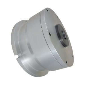
The first step in solving these problems was a visit by Mach III staff to a Wisconsin dairy farm where the exit reel was in use. After gaining a better understanding of the environmental conditions and taking photos of some really adorable calves, they got to work on a new brake design. The corrosion problem was mitigated by a solid housing that completely shielded the brake’s internal components from contamination. The inadequate torque capacity was addressed by enlarging the piston and increasing the friction surfaces from 3 to 4.
Remarkably, Mach III increased the torque by 88% and enclosed the brake while maintaining the footprint of the standard model. This allowed easy retrofit of systems already in use and eliminated any need for BouMatic to redesign the cabinet that houses the brake. The most remarkable feature, however, was the cost. The price of the new brake design was only 10% more than the original.
The solution has kept the client and the cows happy since 2004.

 In our
  Our engineers overcame these challenges with a custom torque limiter that minimized backlash and provided a longer wear life. Featuring fewer components than the Polyclutch® units, our torque limiters incorporated stainless steel components, which reduced wear compared to the aluminum components. The design also included a Shrink Disc to attach the coupling to the shaft, eliminating a wear-prone keyed connection.
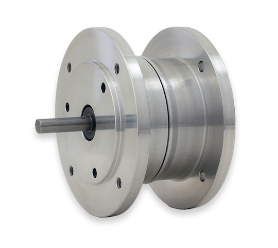 These new miniature brakes include a NEMA frame and enclosed, aluminum housings. In terms of their operation, spring pressure compresses the drive and friction discs, producing a fixed amount of torque. The brake is then released when sufficient air pressure energizes it.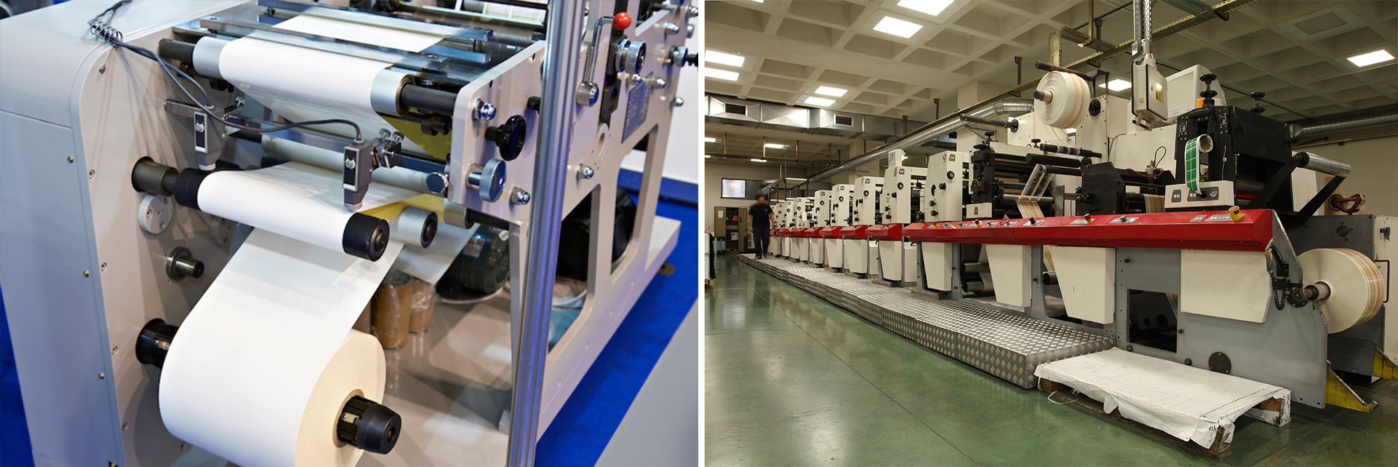
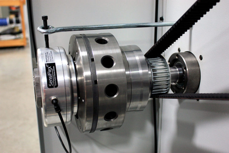 Start with the application details. The most important factor in assuring the maximum service life of a clutch or brake is choosing the right unit for the job based on application details such as cycle rates, revolutions per minute and the torque needed to drive or stop the load. For selection assistance, it’s a good idea to ask for a review by an application engineer at your clutch or brake manufacturer.
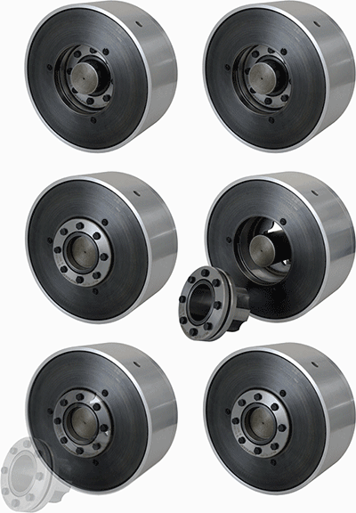 The Resulting Custom Brake Design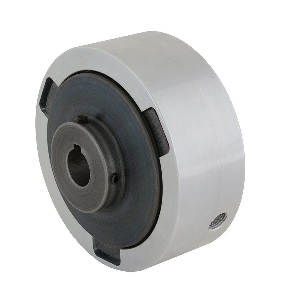
 Sometimes, however, one cow would want to moo-moo-move out of the milking stall more quickly and would push on the reel. That had the unfortunate result of rotating the reel too quickly resulting in the slower cows being bumped on their backsides by the reel. As any dairy farmer knows, an uncomfortable or anxious cow provides less milk. Boumatic first tried to use a hydraulic ram to solve the problem but, according to Anthony Esch, product manager of cow traffic systems, “Adjusting the flow controls for proper speed was difficult, and if air got into the hydraulic ram, it would throw off the braking of the reel.” The problem was presented to Techmaster, Inc., a distributor of Mach III brakes.