Spring-engaged and air-engaged brakes both compress friction and drive discs to restrict motion. However, you might find one is better suited for your application. In a previous blog post, we explored spring-engaged brakes, including their design and use cases. Now, to help you during the brake selection process, we turn to air-engaged brakes.
How Do Air-Engaged Brakes Work?
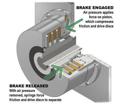
Air-engaged brakes stop rotational motion through the compression of two types of discs — the friction and drive discs — which are normally spaced apart by separator springs. To engage the brake, compressed air pushes the piston rod that compresses the separator springs, pushing both discs together and stopping any motion.
Unlike spring-engaged brakes, the amount of achievable torque in air-engaged brakes isn’t fixed; rather, the more air pressure that is applied, the greater the torque. To disengage the brake, the compressed air is turned off or lowered, allowing the separator springs to expand and push the friction and drive discs apart again.
Ideal Applications
Air-engaged brakes are a good choice for dynamic stopping and cycling applications because they compensate for disc wear over the brake lifecycle. Because the torque isn’t fixed, users can offset friction and drive disc wear by applying more air pressure, pushing the piston rod further and maintaining the same torque.
Air-engaged brakes remain functional until the friction disc wears down to the point that the piston O-ring seals travel beyond the cylinder walls and air leaks out. Keep in mind, these components require a continuous supply of compressed air. Although they can be used to hold a load, if the power fails, so will the brake.
Common Uses
One application for air-engaged brakes is conveyor belts that frequently start or stop. In this example, consider multiple items per zone, creating a load of up to 14,000 pounds with the conveyor moving at 60 feet per minute and stopping every 6 seconds. This application requires the brake to stop the load in 0.25 seconds or within 1.5 inches of motion.
To calculate the minimum brake rating (Tm) required, we’ll need the load weight (W), conveyor velocity (V), coefficient of friction (F) and pitch diameter of the sprocket (Pd). Here are the calculations, where:
W = load weight (14,000 pounds)
V = velocity (60 feet per minute)
G = gravity (32.16 feet per second squared)
T = time (0.25 seconds)
F = coefficient of friction (0.02)
Pd = pitch diameter of drive sprocket (5 inches)
SF = safety factor (1.5)
Tb = braking torque
Tm = minimum safe brake torque rating
\(Tb = ({{(W*V) \over (60*G*T)} – (F*W)}) * {Pd \over 2} = 3,653 \ pound \ inches\)
\(Distance \ to \ stop \ 0.25 \ seconds = ({({V \over 60}) \over 2}) * (12*T) = 1.5 \ inches\)
\(Tm = Tb*SF = 5,480 \ pound \ inches\)
To learn more about air-engaged brakes, visit our product page.