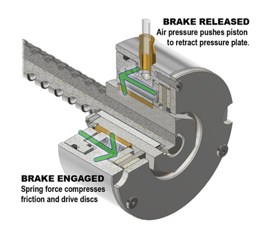
If your application needs a braking system, how do you know whether it’s better to use a spring-engaged or an air-engaged brake? Both are similar in design — they compress friction and drive discs to restrict motion — but each one has its own ideal use cases. In a new two-part blog post series, we’ll explore the key aspects and applications of both brake types, beginning with spring-engaged brakes.
How Do Spring Engaged Brakes Work?
Spring-engaged brakes rely on the compression of two discs — the friction and drive discs. As the disc surfaces meet, the friction force between them stops the rotational motion. The engagement springs expand, forcing a piston to push both discs together and causing the motion to stop. You also need a specific amount of air pressure to push the piston assembly away from the discs and disengage the brake. This air returns the engagement springs to a compressed state, stopping the air supply. Now the brakes are ready again for use. Sometimes, spring-engaged brakes use separator springs to provide a positive separation of the discs to prevent drag and undue friction on the system.
Ideal Applications
The strength of spring-engaged brakes is especially evident in non-cycling applications, where the brake only engages several times an hour or day. Repetitive engagement of the brake can cause the friction and drive discs to thin from wear, requiring the springs to travel further to compress the discs and lowering torque output. In situations where stopping is rare, as in emergency braking systems, spring-engaged brakes are ideal.
A Simple Example

One common application for spring-engaged brakes is holding a lift in position or providing braking force in case of a power failure. The high-capacity lifts that raise automobiles and shipping and air cargo containers are an example. In this case, the lift carries a load of 900 pounds and is driven by a gear motor with a 20-millimeter diameter and five-millimeter pitch ball-screws. The brake needs to hold the lift still when it isn’t in use and will engage when internal sensors detect a zero rotations-per-minute condition in the motor drive.
To calculate the brake parameters for this application example, you’ll need to know the ball-screw lead value, load weight and desired safety factor, where:
L = ball-screw lead (0.1969 inches)
W = load weight (900 pounds)
SF = safety factor
Required holding torque: L x W ÷ 5.65 = 31 pound-inches (lb-in)
Required torque with the safety factor: 31 x 1.75 = 55 lb-in
For more information on spring-engaged brakes, visit our website.