How It Works: Mechanical Friction Torque Limiter
Mach III friction torque limiters are always engaged and transmit a fixed amount of torque from one component to another. They protect the drive and driven components from damage in the event of a torque overload by slipping, so that the amount of torque transmitted from one component to the other does not exceed the pre-set amount. Friction torque limiters are intended for momentary overload only and will continue to slip until the source of the torque overload is cleared, or the machine is shut down. Therefore, a means of detecting the torque overload must be in place.
BASIC CONNECTION
- Either the SHAFT on which the torque limiter is mounted or another shaft connected to the SLEEVE (by means of sprockets and roller chain, pulleys and belt, or a coupling) can be the input source.
- The torque limiter is capable of rotation in both clockwise and counterclockwise directions.
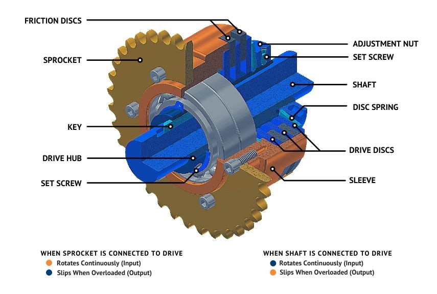
- The DRIVE HUB slides over the SHAFT. The drive hub includes a keyway which corresponds to the keyseat in the SHAFT. When a KEY is in place, the two members are connected. The clutch is locked onto the SHAFT with SET SCREWS.
- Lugs (tabs) on the outside diameter of the FRICTION DISCS fit into corresponding slots in the SLEEVE. The inside diameter of the DRIVE DISCS are connected to the DRIVE HUB via gear teeth or other drive geometries.
- The SLEEVE includes a precision machined pilot onto which a sprocket, pulley, sheave, coupling or adapter can be attached.
OPERATION WITHOUT OVERLOAD
- A DISC SPRING located below the ADJUSTMENT NUT applies a constant, fixed amount of force to the DRIVE DISCS and FRICTION DISCS.
- The amount of torque transmitted is fixed by the force applied by the DISC SPRING which is adjusted by loosening or tightening the ADJUSTMENT NUT. When desired torque setting is achieved, a SET SCREW locks the ADJUSTMENT NUT in place.
- The FRICTION DISCS and DRIVE DISCS remain in contact keeping the input and output members rotating as one until a torque overload is experienced.
UPON OVERLOAD
- During a torque overload, such as in the case of a jam preventing rotation of the output members, the pressure applied by the DISC SPRING is overcome and the output members slip which prevents a spike in torque from transmitting to the input component.
- Slip can also occur in the opposite direction, so that the input members would slip to prevent the torque overload from transmitting to the output component.
- The unit does not disengage in the event of an overload. It continues to slip until the source of the torque overload is cleared, or the machine is shut down.