Skip to Content
Mach III Clutch Inc.
Menu
Request A Quote
  • Custom Products
    • Custom Brakes
    • Custom Servo Brakes
    • Custom Clutches
    • Custom Clutch Brakes
    • Custom Torque Limiters
    • Custom Design Process
  • Standard Products
    • Brakes
    • Clutches
    • Torque Limiter
    • SensiFlex® Tension Control
    • Combination Clutch-Brakes
    • Miniature Series
    • Power Drill Torque Couplings
  • Applications Blog
  • Resources
    • How Our Products Work
      • Installation And Use
      • Selection Guidelines
      • Product Manuals
    • Submit Specs
    • How To Order
      • Conditions Of Sale
      • Distribution Policy
      • Identifying A Product
      • Repair Parts Kits & Service
      • Return Policy
      • Request A Quote
      • Mach III Product Warranty
  • Contact Us
    • Contact Info
    • Engineering Assistance
    • Careers
 
  • How Our Products Work
  • Installation And Use
  • Selection Guidelines
  • Product Manuals

How It Works: Air Engaged Friction Brake

Mach III pneumatic brakes are designed to perform two functions: dynamic braking (bringing a rotary load to a stop) and holding (preventing the rotation of a load). This type of brake is engaged with air pressure and is positively disengaged by spring pressure when air pressure is absent.

Basic Connection

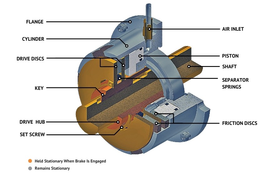
  • The DRIVE HUB slides over the SHAFT. The drive hub includes a keyway which corresponds to the keyseat in the SHAFT. When a KEY is in place, the two members are connected. The brake is locked onto the SHAFT with SET SCREWS.
  • FLANGE mounted brakes such as the one shown must be connected to an anti-rotation restraint such as a machine frame or bracket with cap screws or shoulder bolts. A precision machined bolt pattern in the FLANGE is provided for this purpose.
  • Lugs (tabs) on the outside diameter of the FRICTION DISCS fit into corresponding slots in the CYLINDER. The inside diameter of the DRIVE DISCS are connected to the DRIVE HUB via gear teeth or other drive geometries.
  • The brake is capable of rotation in both clockwise and counterclockwise directions.
How It Works

Energizing The Brake

  • Compressed air supplied to the brake through the AIR INLET applies force to the PISTON, which in turn applies force to the FRICTION DISCS and DRIVE DISCS.
  • Once adequate pressure is achieved to collapse the SEPARATOR SPRINGS located between the FRICTION DISCS and DRIVE DISCS, the discs come into contact and create the friction that transmits torque.
  • Torque transmitted is linear in proportion to the air pressure (PSI, BAR) applied; more air pressure = higher torque output.
  • The maximum recommended air pressure for most Mach III products is 80 PSI.

Disengaging The Brake

  • The FRICTION DISCS and DRIVE DISCS remain in contact and holding the SHAFT until compressed air is no longer supplied.
  • In the absence of air pressure, the SEPARATOR SPRINGS expand to push the FRICTION DISCS and DRIVE DISCS apart. When the discs are fully separated, the brake is fully disengaged.
  • Timing for full disengagement is short but depending upon the cycle rate of the application, it is sometimes advisable to install a quick exhaust port to allow the air to exit the brake more quickly.
Mach III Clutch Inc.

Mach III Clutch Inc.

1580 Lake Street, Elmira, New York 14901

Phone: 859-291-0849

Twitter LinkedIn Facebook
  • Privacy Policy
  • Terms of Service
  • Sitemap

© 2026 Mach III Clutch Inc.

All Rights Reserved | Site created by Thomas Marketing Services

3D Model Request

"*" indicates required fields

This field is for validation purposes and should be left unchanged.
Model Type:*
This field is hidden when viewing the form