
How It Works: Air/Air Stop and Start the Shaft Clutch-Brake
Mach III pneumatic clutch-brakes transmit rotary motion from a constantly rotating shaft to a shaft that is required to rotate intermittently. When motion is not required, the clutch-brake holds the shaft stationary. This model requires two separate air signals; one to supply air pressure to energize the clutch and another to supply air pressure to apply the brake. It is appropriate for applications where equal clutch and brake torque capacity is required. Care should be taken when using two air signals to ensure that there is no overlap that would allow simultaneous engagement of the clutch and brake.
Basic Connection
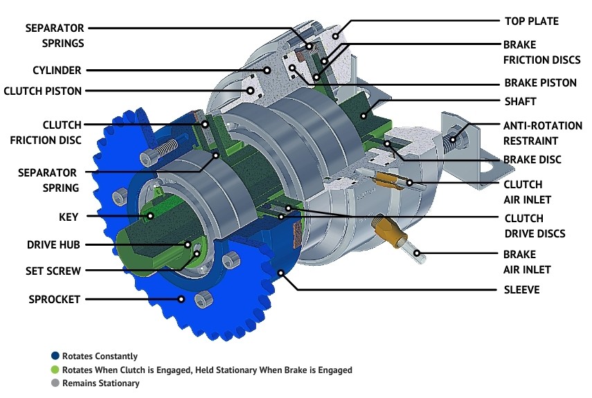
- The DRIVE HUB slides over the SHAFT. The drive hub includes a keyway which corresponds to the keyseat in the SHAFT. When a KEY is in place, the two members are connected. The clutch-brake is locked onto the SHAFT with SET SCREWS.
- Through-shaft mounted clutch-brakes such as the example shown must be connected to an ANTI-ROTATION RESTRAINT such as a machine frame or bracket to react the brake torque.
- Lugs (tabs) on the outside diameter of the CLUTCH and BRAKE FRICTION DISCS fit into corresponding slots in the SLEEVE and TOP PLATE. The inside diameter of the CLUTCH DRIVE DISCS and BRAKE DISC are connected to the DRIVE HUB via gear teeth or other drive geometries.
- The SLEEVE includes a precision machined pilot onto which a sprocket, pulley, sheave, coupling or adapter can be attached.
- The clutch-brake is capable of rotation in both clockwise and counterclockwise directions.
Energizing And Disengaging The Clutch
- Once adequate pressure is achieved to collapse the SEPARATOR SPRINGS located between the CLUTCH FRICTION DISCS and DRIVE DISCS, the discs come into contact and create the friction that transmits torque to the SHAFT.
- The amount of torque transmitted is linear in proportion to the air pressure (PSI, BAR) supplied; more air pressure = higher torque output.
- The maximum recommended air pressure for most Mach III products is 80 PSI.
- The CLUTCH FRICTION DISC and DRIVE DISCS remain in contact rotating with one another until compressed air is no longer supplied to the clutch.
- In the absence of air pressure, SEPARATOR SPRINGS located between the CLUTCH FRICTION DISCS and DRIVE DISCS force them apart, pushing the neutral air out of the CLUTCH PISTON. With the discs separated, the clutch is fully disengaged.
- Timing for full disengagement is short but depending upon the cycle rate of the application, it is sometimes advisable to install a quick exhaust port to allow the air to exit the clutch more quickly.
Energizing And Disengaging The Brake
- Compressed air supplied to the BRAKE AIR INLET moves the BRAKE PISTON backward, forcing the BRAKE FRICTION DISCS and BRAKE DISC to squeeze together.
- Once adequate pressure is achieved to collapse the RELEASE SPRINGS located between the BRAKE FRICTION DISCS and BRAKE DISC, the discs come into contact and create the friction that transmits torque.
- The amount of torque transmitted is linear in proportion to the air pressure (PSI, BAR) supplied; more air pressure = higher torque output.
- The maximum recommended air pressure for most Mach III products is 80 PSI.
- The BRAKE FRICTION DISCS and DRIVE DISC remain in contact, preventing rotation until compressed air is no longer supplied to the brake.
- In the absence of air pressure, RELEASE SPRINGS located between the BRAKE FRICTION DISCS and DRIVE DISC force them apart, pushing the neutral air out of the BRAKE PISTON. With the discs separated, the brake is fully disengaged.
- Timing for full disengagement is short but depending upon the cycle rate of the application, it is sometimes advisable to install a quick exhaust port to allow the air to exit the brake more quickly.