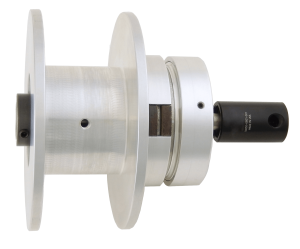
Power-Off Brake For Short Axial Shaft
With little more than 2 inches of shaft extending from the machine frame to work...
Engineering, Production, Sales, and Product Support all under one roof.
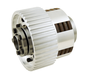
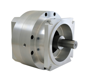
Air and spring engaged friction brakes and clutches and mechanical torque limiters for motion control applications with torque requirements up to 60,000 pound inches and shaft sizes to 3.5 inches.
From slight design modifications to completely unique, clean-sheet creations, we can present you with a customized design solution in about 48 hours.
We specialize in high variation, low quantity production. All products are built-to-order, allowing even catalog models to be bored to fit the exact shaft and key size required.
Every purchase order we receive is confirmed with a ship date that we meet or beat 98% of the time. Lead times for Standard Products: 2 to 5 weeks. Custom Products: 3 to 6 weeks.
Without fail, we always provide detailed models, spec sheets, easy-to-read quotations, prompt order acknowledgements and accurate shipping documents.
Mach III products are used in a wide array of machines and industries to connect and disconnect, stop, hold, maintain tension control and protect machine components from overload.
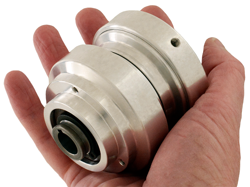
Ten Small Brakes, Clutches and Torque Limiters for shafts from 5/16 to 1/2 in and 7 to 12mm