Selection Guidelines
Torque Capacity, Ratings and Output
Mach III products use friction to transfer torque from one rotating component of a machine to another (clutches and torque limiters) or from a rotating component to a machine frame (brake). Friction is created either by compressed air force or spring force squeezing a set of discs into contact. The disc set includes one or more friction discs and one or more drive discs that are alternately attached to the components which rotate constantly and those that do not.
Torque Capacity
The amount of torque that a unit is capable of transferring is determined by the following equation:
T = F x Rm x μ x N
Where:
T = Torque (lb-in)
F = Force (lb)
Rm = Mean Radius of friction surfaces (in)
µ = Coefficient of friction
N = Number of friction surfaces
Torque Ratings and Torque Output
Mach III publishes a torque rating for each product expressed in pound inches (lb.in.). All torque ratings are dynamic.
Air Engaged Clutches and Brakes
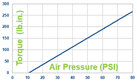
The torque rating of air applied clutches and brakes is determined by performing the calculation shown above, where F = the maximum air pressure at which Mach III recommends the product be operated. For most products, the maximum recommended compressed air pressure is 80 PSI.
Torque output of an air engaged clutch or brake is linear in respect to the air pressure applied. Below is the torque graph for the B3F2R-STH brake. In this example, it takes 11 PSI to overcome the force of the separator springs and engage the brake.
Spring Engaged Clutches and Brakes
The rating of spring applied clutches and brakes is determined by performing the calculation shown above, where F = the force applied by the springs contained within the unit. Compressed air pressure is required to release the product, therefore, a release pressure is also specified for each spring engaged clutch and brake.
The torque output of a spring engaged clutch or brake is not variable.
Torque Limiters
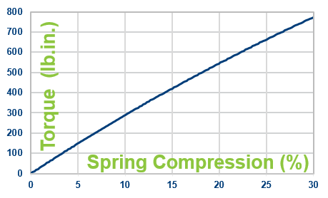
Friction torque limiters are similar to spring engaged clutches and brakes in that the rating of a friction torque limiter is determined by performing the calculation shown above where F = the spring force applied. The force, however, can be changed by loosening or tightening an adjustment nut. The range of that adjustment is limited on the upper end by the tensile strength of the friction discs. Mach III, therefore, lists a maximum recommended torque setting for each friction torque limiter.
Below is the torque graph for the T3B2H-STL friction torque limiter. The torque graph stops at 30% spring compression because that is the approximate point at which the maximum recommended torque setting of 792 pound inches is reached.
New vs. Burnished Torque Output
The torque output of a new friction clutch, brake or torque limiter can be up to 40% less than the published torque rating. To achieve full design torque, a unit must be cycled under load to burnish the friction surfaces. The exact number of cycles varies by application.
Product Selection Basics
The following represents the general factors to consider when selecting a clutch, brake or torque limiter for an application. Not every condition or circumstance is covered here. It is strongly recommended that all applications are reviewed with a member of the Mach III engineering team. Damage caused by misapplication is not covered under the terms of our warranty.
Torque Requirement
Required torque is the most important factor in selecting a clutch, brake or torque limiter for an application. To calculate the torque requirement:
T = (HP X 63,000/RPM) SF
Where:
T = Torque (lb-in)
HP = Horsepower of the motor
RPM = Revolutions per minute at the clutch, brake or torque limiter
SF = Safety factor
Safety Factor
It is not recommended to select a unit for use at its maximum rated torque for continuous duty. As a general guideline, a safety factor (also known as a service factor) of 1.5 to 2 is recommended when selecting a clutch, brake or torque limiter. Increased service factors are advised for systems including any of the following:
-
- Gas or diesel engine drives
- High inertia loads
- Rough driven loads
- High cycle rates
Operating Speed (Revolutions Per Minute)
A maximum recommended operating speed is listed on the PDF detail sheet available for each Mach III product listed on this website. For applications with RPMs exceeding these recommendations, consult Mach III’s engineering department. Higher RPM allowances can sometimes be achieved through customized design and or balancing.
Operating Environment
Temperature: Mach III catalog products are rated for operation in environments between -10 to 225 degrees Fahrenheit (-24 to 107 degrees Celsius). Temperatures outside this range are achievable with customized designs.
Contaminants: Moisture, particulates, chemicals, solvents and lubricants can damage the friction linings, cause premature wear of components and malfunction. Design accommodations may be necessary when the potential for contamination exists.
Food Production & Clean Rooms: The wear of friction discs produces particulates. Design accommodations may be necessary when using a Mach III product in these special environments. Products can also be manufactured with food grade and spark resistant finishes.
Thermal Capacity
Connect, Disconnect, Stopping and Starting Applications: Clutches, Brakes and Combination Clutch-Brake Combinations generate heat during each engagement. Overheating can occur in cases where high cycle rates are combined with high engagement RPM, high inertial loads and/or clutch and brake overlap. Consult engineering if these conditions exist in your application.
Tension Control (Unwind and Rewind) Applications: Brakes and clutches used in continuous slip applications must be selected based on their ability to dissipate heat as well as provide the required torque. SensiFlex® clutches and brakes are designed specifically for this application. Thermal Horsepower vs. RPM graphs are provided for all SensiFlex® products. To calculate the required thermal horsepower for a tension control application:
Thermal HP = Required Torque x Slip RPM / 63,000
Overload Protection (Slip) Applications: Friction torque limiters slip when overloads are experienced which generates heat. They are designed to protect drive components against momentary overloads only. Prolonged slip of the torque limiter will result in overheating.
Shaft Size
Each Mach III catalog clutch, brake or torque limiter, with the exception of NEMA frame models, is available in a range of Imperial and Metric bore sizes. The maximum bore size possible for each model is shown in the product detail tables. The bore range for each product (minimum to maximum) is shown on the PDF detail sheet. The maximum bore size listed represents the largest bore possible with a standard square (Imperial) or rectangular (Metric) keyway. In some cases, products can be bored to 1/16 (0.0625) inch larger than the published maximum with a shallow keyway. Consult engineering if a larger than published bore size is required.
Bore Tolerances = Class RC3
Mounting Considerations
Anti-Rotation Restraint: Through-shaft model clutches and all clutch-brakes require installation of an anti-rotation restraint. This restraint prevents rotation due to drag in the bearings contained within the unit, and in clutch-brake models, reacts the torque when the brake is applied.
Click Here to dowload a PDF file showing proper anti-rotation arm installation examples.
Orientation: Most Mach III products are designed for use in a horizontal position. Modifications may be required when operating a unit in a vertical position. All vertical mount applications should be reviewed with Mach III engineering.
Shaft-to-Shaft Connection: For shaft-to-shaft coupling applications, flexible coupling models are recommended. Where rigid couplings are used, great care must be taken to assure proper alignment.
Installing Sprockets, Pulleys and Sheaves: The pilots of Mach III clutches, clutch-brake combinations and torque limiters are precision machined to Class RC5 tolerance for the installation of a mating component. The pilot dimensions can be found on the PDF detail sheets for all catalog products shown on this site. For pilot dimensions of non-catalog models (product identification numbers ending in numeric characters versus alphabetic characters), contact Mach III.
Safety Considerations
Mach III products include rotating components and should be guarded according to OSHA requirements and other applicable federal, state and local regulations. It is the responsibility of the user to provide the necessary guarding.