Installation And Use
Product Identification
Identification numbers and the date of manufacture are stamped into the housing, generally on the end of the assembly containing the air inlet. If the ID number will be inaccessible after installation, it may be helpful to record the number and manufacture date for future reference.
Click Here to see the visual guide to locating the identification number and information regarding Mach III part number formats.
General Installation Guidelines
Below are the general installation guidelines that apply to most Mach III products. For individual product installation instructions, visit the Product Manuals page.
Installation of Pulleys, Sprockets, Sheaves or Other Accessories
- Except for NEMA or IEC frame models and some custom products, all Mach III clutches, combination clutch-brakes and torque limiters include a precision machined pilot onto which a timing belt pulley, roller chain sprocket or other accessories are mounted for connection to mating machine components.
- All pilots are machined to a Class RC5 tolerance unless otherwise specified.
- Mach III offers the service of providing factory machined and installed accessories. Please contact customer service for information and pricing.
- If accessories are to be installed in the field, pilot dimensions for each Mach III catalog product can be found on the PDF detail sheet which are available on this website.
- For pilot dimensions of non-catalog models (product identification numbers ending in numeric characters versus alphabetic characters), contact Mach III.
- It is recommended that users installing accessories in the field consult our e-book, Mounting Sprockets and Pulleys on Pilot Style Clutches, to avoid errors which may diminish performance and reduce the wear life.
Torque Setting
The torque setting of Mach III friction torque limiters is adjustable. The torque value can be pre-set at the factory or set in the field. When setting or re-setting the torque value, please consult the product manual for the correct torque setting procedure. Product manuals for catalog products can be obtained on the Product Manual page or by contacting Mach III Engineering.
Orientation
- Most Mach III products are designed for use in a horizontal position. Modifications may be required when operating a unit in a vertical position.
- All vertical mount applications should be reviewed with Mach III engineering.
Shaft Preparation
The majority of Mach III products contain a hub which is connected to the shaft with a key and then locked in place with set screws. The hub is bored to fit a precision plug gauge for the specified shaft size and is cut with a keyway. The keyway is sized to published standards unless a non-standard keyway is requested. Coupling models contain two bores with keyways. NEMA and IEC frame models and some custom designs contain a both bore with keyway and an output shaft with a keyway.
The diagram below illustrates a typical connection arrangement.
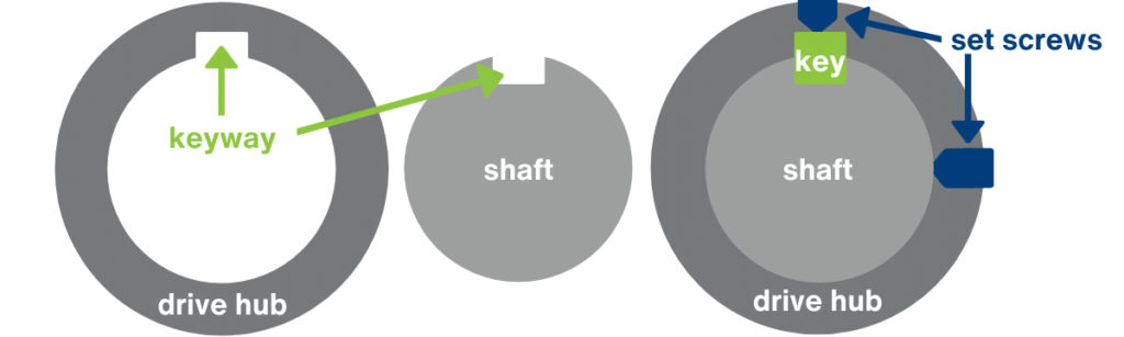
-
- The key is not provided by Mach III, except for with some custom and C-Face products.
- Set screws are included.
All bores are machined to a Class RC3 tolerance and should slide fit onto the shaft. Before placing a unit on a shaft, assure that the shaft is free of burrs and nicks. Mach III ships a packet of anti-seize lubricant with all shaft-mounted products except with custom models that utilize shrink-disks or Morse tapers for connection. Anti-seize lubricant should be applied to the shaft before the unit is installed. If the clutch does not slide fit onto the shaft, both the bore and the shaft should be checked. Products should never be hammered onto the shaft.
Alignment
Chain and Belt Positioning: There must be proper alignment of any pulley, sprocket or sheave with its corresponding timing belt, roller chain or v-belt to avoid premature wear and improper function. Misalignment can also cause a clutch, clutch-brake or torque limiter to walk off the shaft. Refer to the e-book Mounting Sprockets and Pulleys On Pilot Style Clutches for more information.
Shaft-to-Shaft Connection: For shaft-to-shaft coupling applications, flexible coupling models are recommended. Mach III flexible couple models accommodate up to 3 degrees of angular misalignment and up to 0.040 parallel offset between shafts. Where rigid couplings are used, great care must be taken to assure full alignment.
Anti-Rotation Restraint (Pertains to Through Shaft Clutches and Combination Clutch-Brakes Only)
- In Mach III through-shaft mounted clutches and combination clutch-brakes, the cylinder portion of the unit is designed to remain stationary. Due to friction in the bearing housed in the cylinder, this member will rotate unless an anti-rotation arm (also known as a reaction arm) is installed. A threaded hole is provided in the cylinder for the installation of this arm.
- The air fitting should not be used as the anti-rotation restraint.
Click Here to download Mach III’s guide to proper anti-rotation restraint connection.
Flange Connection (Pertains to Brakes and Some Custom Model Clutches and Torque Limiters)
- Drill and tap holes in the mounting surface corresponding to the type and bold circle of the clearance holes on the brake flange.
- When Mounting Surface Is Absolutely Perpendicular To The Shaft: Tighten all bolts uniformly to the torque recommended for the bolt size using proper Loctite® (or equivalent) compound to assure a permanent mount.
- When Mounting Surface Is NOT Absolutely Perpendicular To The Shaft: Attach the brake to the mounting surface using shoulder bolts in the provided holes, or pins in the provided slots to allow the brake housing to float.
Air Supply and Connection
- Compressed air supplied to Mach III products should be dry, filtered and regulated.
- Lubrication of the air supply is NOT necessary.
- For best response, control valves should be located as close to the unit as possible.
- Higher cycling applications or any applications where fast exhaust times are necessary should utilize a quick exhaust valve.
- Connect flexible tubing to the air inlet using an appropriately sized air fitting and thread sealing compound. Do not use rigid piping.
- The air fitting should not be used as the anti-rotation restraint.
Guarding
Mach III products include rotating components and should be guarded according to OSHA requirements and other applicable federal, state and local regulations. It is the responsibility of the user to provide the necessary guarding.
Operation
Final Inspection and Testing
Cycle the unit with the machine off to check for air leaks and to ensure proper engagement and release.
Spring Engaged Clutches and Brakes
- Spring applied products transmit a fixed amount of torque and require the application of compressed air to release.
- Consult the unit’s PDF detail sheet or the product assembly drawing to obtain the amount of air pressure that is required to fully release the clutch or brake.
- Applying air pressures lower than the stipulated release pressure may allow the product to operate while partially engaged which will result in overheating and damage.
Air Engaged Clutches and Brakes
- Air applied products transmit torque in linear proportion to the air pressure applied.
- For most products, the maximum recommended compressed air pressure is 80 PSI.
- Below is the torque graph for the B3F2R-STH air applied brake. In this example, it takes 11 PSI to overcome the force of the separator springs and engage the brake.
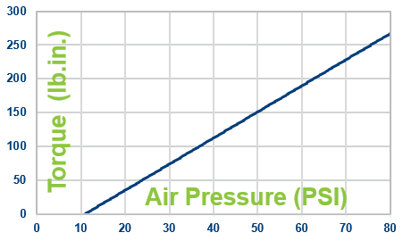
- To calculate required air pressure:
PSI = Required Torque x 80 / Design Torque
Torque Limiters
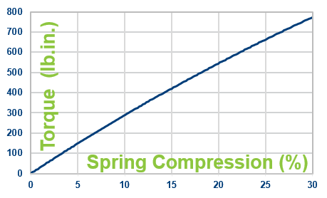
The torque output of Mach III friction torque limiters is fixed by the amount of compression of the spring and can be adjusted in the field by tightening or loosening the adjustment nut. When setting or re-setting the torque value, please consult the product manual for the correct torque setting procedure. Product manuals for catalog products can be obtained on the Product Manual page or by contacting Mach III’s engineering department. The range of torque output is limited on the upper end by the tensile strength of the friction discs. Mach III, therefore, lists a maximum recommended torque setting for each friction torque limiter. Setting the torque higher than the recommended setting will result in friction disc failure.
Below is the torque graph for the T3B2H-STL friction torque limiter. The torque graph stops at 30% spring compression because that is the approximate point at which the maximum recommended torque setting of 792 pound inches is reached.
New vs. Burnished Torque Output
The torque output of a new friction clutch, brake or torque limiter can be up to 40% less than the published torque rating. To achieve full design torque, a unit must be cycled under load to burnish the friction surfaces. The exact number of cycles varies by application.
Safety Factor
Clutches, brakes and torque limiters should not be operated at their maximum rated torque for continuous duty. As a general guideline, a safety factor (also known as a service factor) of 1.5 to 2 is recommended.
Operating Speed (Revolutions per Minute)
A maximum recommended operating speed is listed on the PDF detail sheet available for each Mach III product listed on this website.
Troubleshooting
The most efficient way to troubleshoot an operation problem is to contact Mach III Engineering. They can ask a series of questions that typically leads to a quick identification of the problem and a solution.
Maintenance and Repair
Routine Maintenance
Mach III products require little or no routine maintenance when:
-
- When properly selected for the application
- Installed according to guidelines
- Operated with clean, dry and regulated compressed air
Repair Kits
- Occasional replacement of wear parts, such as friction discs, springs and seals may be required.
- High cycling and tension control applications will require more frequent replacement of wear parts.
- Repair kits are available for all products which contain all of the wear parts contained within a unit.
- Contact Mach III Customer Service or submit an RFQ to obtain a part number and pricing.
Other Parts
For more extensive repair requirements, contact Mach III to obtain a parts list and pricing for the parts you required.
Factory Evaluation and Repair (Warranty and Non-Warranty)
It is not possible for Mach III to quote a repair or determine that a problem is covered by our warranty until we have evaluated the unit. Evaluations are performed at no charge. Once complete, a summary of the problem and quotation for repair will be provided. If you are interested in sending a unit to Mach III for evaluation, please contact Customer Service to obtain the Return Authorization document that must accompany the shipment.